S100 Computers

Home S-100 Boards History New Boards Software Boards For Sale
Forum Other Web Sites Quiz Index    

Debugging S-100 Boards

From time to time I get calls or e-mails from people that have an old S-100 system that is "dead" and ask for advice on how to get it going again. Indeed over the years I have blown a few of my own systems and had to resuscitate them.

There are numerous reasons why an S-100 computer dies. It can be a very frustrating experience to power up and see a blank screen. However one of the great advantages of the S-100 bus system is that the various computer components can be isolated, reconfigured and checked out individually to quickly locate the problem(s).

Causes of Failure.
There are clearly many, but surprisingly many fall into a few categories:-

Bad Connectors. 
This is often the most overlooked cause of a failure. We often tend to think of complex reasons why the system died. Random characters on a screen, the computer works sometimes or dies unexpectedly.  After you simplify your system by removing all but essential cards (see below), check one by one:-
  The power connectors going to the power supply
  The fuses and their connections
  Make sure all remaining boards are reseated in the bus
  Clean each S-100 board connector with "TV Tuner Spray"
  Check the Keyboard connector is correct
  Check the video cables are correct
  Check your voltage regulators are supplying power

Heat
While on voltage regulators, these are a unique feature of the S-100 bus. Most bus cards utilize a regulate central power supply. The main heat source inside your S-100 box is the cooling fins from the 5V regulators. Now the original S-100 systems all delivered 8 Volts or greater (pins 1 & 51) to these regulators. That was in fact the IEEE-696 specs. The regulator burned the excess voltage off as heat to get to 5 volts -- thereby heating your room as well.  Fortunately mostly of these regulators will work with far less than this. IF you can bring your power supply down to 7 Volts there is a great heat saving. I use a switching power supply and so can do this. With the old linear transformer based supplies its not that easy. Some have primary voltage taps which allow you to drop output voltages 10%.   BTW, be sure you know what your are doing if you do this. Check all voltages with no cards first. Alternatively if you have a high voltage problem, to you can obtain a "Japanese Voltage Converter" (available at many places on the web) which drops your input from 120 Volts to 100 Volts. Just plug your whole computer into it.

Dirt
More common than you might think.  Unfortunately the S-100 bus has 100 connections per board. A microscopic thin film of corrosion on a few pins can cause havoc in the system. The give away is if you juggle the boards it works for a while.  On old systems remove all boards. Use compressed air to bow away all dust and particles. Wipe each and every board with "TV tuner" (available at Radio Shack etc.) to shine up each gold pin. Use a cloth towel to wipe each board.  I spent a whole day once trying to debug a system only to find out the cause was a small solder chip had fallen down into the S-100 socket and was shorting two pins.  Check each and every socket before and after blowing air into them.

Bad Sockets
This is really a subset of the above first item. Unfortunately many of the early S-100 boards were manufactured with less than high quality sockets or were built by hobbyists on a tight budget.  These sockets did not form "gas tight" junctions with the IC pins. Over time corrosion/dirt can get between the socket pin and the IC pin. This leads to failure.

As a rule when cleaning up old boards of dirt as described above, each IC should be reseated in its socket. Just pressing down is not enough. Raise it up and press it down firmly into the socket.  The are varying views as to whether it is best to solder IC's directly into a board (more reliability) or to use sockets (where chip replacement/debugging is easy).  In some case as a compromise I have soldered in IC's on most of the board but socketed IC's for chips that drive the bus.  The latter are most lightly to be "blown out" by board address conflicts etc.

Bad Caps and other Components.
A fairly common cause of failure with S-100 boards are the 30+ year old Tantalum capacitors.  Unfortunately they often do not dead short out (where you can see, smell and feel the short), instead the leak. This causes havoc on a board. It works sometimes but as the board warms up it fails.   I had a Versafloppy II board like this which cost me two days trying to figure out the problem. It would work each morning for about 30 minutes and then get unreliable. Unreliable it the worst thing you can have, since it takes time for you to know you fixed a problem.  The tip off came when I noticed if I put the board in my -20 freezer for 30 minutes any time during the day it worked rock solid until it really warmed up.  Since then I learned my lesson. I now always have at hand a can of Freon freeze spray. I froze sections of the Versafloppy board and quickly realized that a faulty Tantalum capacitor was the problem. 

Also be careful if you acquire a working board from somebody else and plop it into your system. If your 8, 16 or -16 volt lines are higher than theirs/specs, you can pop a voltage regulator capacitor.  I had this happen with two Godbout boards a few years ago before I went to my carefully regulated switching power supply. In both case those small plastic caps actually went on fire!  Somewhat related, some people and manufactures removed the voltage regulators from all the boards in their system and supplied +5 volts on S-100 pins 1 & 51. This works fine (less heat) but is a disaster to the board if you put it in a standard S-100 system. All chips on the board will be fried.

Board Placement
This one is less common but sometimes is relevant if you are pushing your system up to high clock frequencies.  Particularly with multi-CPU/master-slave systems.  I like to keep my CPU(s) in the center of the bus with the RAM boards nearby.  Slow I/O boards and other boards are at the ends. I use an active terminated S-100 bus, board placement is probably more important in a non terminated and/or larger motherboard.

The MWRT Signal
The early IMSAI, Altair and the like systems  generated the important memory write signal on the computers front panel. The signal was put out on S-100 pin 68. It was generated from the sSOUT signal (pin45) and sWO (pin 97).  To accommodate computers that did not have a front panel, S-100 manufactures had an option whereby the MWRT signal could be generated on the CPU board itself. This was done with a jumper on the board; This is the way in fact it should have been. The external generation on MWRT is a true vintage carry over from the early days.   Anyway, it's impotent to make sure only one option is uses (front panel or CPU board). A common mistake is for people having no MWRT signal on the bus.  Since the first thing a computer monitor does is setup the Stack in RAM (i.e. a memory write) the computer will not sign on.

Pulling Out Cards With The Power On
Another common problem is putting cards in or taking them out of the system before the power to the bus has dropped to zero.  Particulary with systems with only a few cards, it takes often up to 30 seconds for the +8 volt line to drain down to zero when the power is turned off.  You can easily blow bus drivers on cards this way.  Its hard to do, I know, when you have other problems needing your attention. One solution often done is to have large 1 Watt, 10 Ohms "bleed" resistors across the top of the system filter capicitors/power supply. These will cause the powwer to drop fast when the system is turned off.


First Steps
The first thing to do if your system fails is not to panic.  I don't know how many times I rushed into things flipping boards in and out, flipping configuration switches etc. only to make things worse. I know better now. I stand back and think.  You will need a few common tools. A voltmeter and a digital logic probe is essential. You can get these at any electronic store.  A good scope or better still a PC-based multi-input logic analyzer really helps in difficult case.  I use the one called Saleae, see (www.saleae.com). It has really helped diagnose problems in fast and/or complex systems.

Is There Power
Seems obvious, does anything light up, and while it is easy to see the +8 volt driven components do not forget to check you have +16 and -16 volts on pins 2 and 52. The latter problem cost me a whole morning a few years ago. 

What was the Last Working system
Have you just add a new board or reconfigured a current one. If so, chances are you have either a bad board or a port and/or memory conflict with another board exists in your system.  In larger systems its is easy to forget what port is assigned to each board. I have learned the hard way to keep and mention a log of ports used.   If you have a 16 bit system or are using extended memory addressing in an 8 bit system (e.g. CPM3), remember that the older 16 bit addressed S-100 RAM boards will overlap the IEEE-696 24 bit addressed boards and can cause a conflict if mixed. Likewise for I/O ports.  The original 8080 & Z80 CPU's used 8 bit ports (0-FFH). 16 bit CPUs will use all 16 bits, but older S-100 I/O boards will ignore the upper 8 bits and activate in any range from (00xxH to FFxxH).

Start with a Minimal System Only
As I said before on of the great advantages of the S-100 system is you can swap and remove components easily. If a IBM-PC clone motherboard dies you are essentially dead in the water.  How minimal to make the system really depends on how dead your system is. If your system will not even sign on to your monitor (serial port terminal or video board) you need to start from basics.  Strip everything out first. Check the bus pins 1 & 51 are at least 7 volts. Check pin 2 is at least 14 volts and pin 52 is at least -14 volts. Clean the CPU card as described above and insert it in the bus. 

S-100 CPU cards come in two basic types. Those that have an onboard ROM that the CPU jumps to on reset (e.g. Intersystem's, Compupro, Northstar,...) or those that do not (e.g.. TDL, Cromemco, IMSAI, Altair). Some companies had both types.  Anyway if your CPU board does not have an onboard ROM add just that board as well as the CPU card to your system.

Power up your system. First look and smell for overheating components. Capacitors, a power dropping resistor, IC's. Remember except for the voltage regulator nothing ther should be too hot to touch. Next you need to see is that any life at all. Check the following important S-100  pins:-

Pin 24, the master clock. should pulse continiusly with a logic probe, square wave with a logic analizer.  If nothing back track on the circuit board to where the signal is generated. Also be sure the CPU is getting the signal (pin 6 on a Z80).
Pin 75, hit the reset button on your computer. This line should pulse low but normally remain high.  Check a single sharp pulse is getting to the CPU (pin 26 on a Z80).  Pulling POC low (S-100 pin 99) should do the same thing.

On reset, the 8080 & Z80 CPU starts at address space 0000H, (The 8086 like CPU's etc. are different), so your CPU will try and read whatever is at that location. Since almost every piece of software for 8 bit systems runs in low memory some way was need to shift the CPU away from that location and address the on board ROM monitor at startup. Various schemes were used to force the CPU at reset to "Jump to the monitor ROM location in memory". These ROMs are normal in high memory at E000H or F000H.  The good news is we don't really have to worry about it at the moment. No matter what, the CPU should pulse its RD line low (pin 21 on a Z80) and on a Z80 the MRQ line should also go low (pin 19).  If this does not happen you probably have a CPU problem. Check it is getting 5 volts (pin 11 on a Z80).  Look at your schematic for your Monitor ROM. It usually is a 2708, 2716 or 2723 EPROM type.

Locate the OE (output enable pin, 20 for these EPROMS). When you hit the reset button pin 20 of the EPROM must pulse low.  If your EPROM is not on the CPU board but the second S-100 board in your system, check there. Also in that system check the S-100 sMEMR line (pin 47) pulses HIGH.  Note this may not be the case for onboard ROM/CPU arrangements.   If you don't see this signal first check you have the jumper/switches set correctly for "Power on Jump".   Failing that you will have to step by step trace back from the OE PROM pin and see where the signal is getting lost.

Assuming then we can access the EPROM the next thing is to have it programmed to do something simple. I have 3 types of EPROMS here (in 2708, 2716 and 2732 chips) which has saved my neck many times over the years. I know its a bit of a chicken and egg situation if you don't have a functional system. But somehow get these EPROM burnt either via PC-base software/hardware or via a friend. If you have a functional system do them now, you may appreciate it later.

Testing EPROMS
The first EPROM is the "HALT prom".  It is an EPROM with nothing more than 8080/Z80 op-codes 76H (HALT) in it.  When any 8080/Z80 CPU hits a ROM anywhere in the 64K address space and sees 76H it will immediately put the CPU into a HALT state -- forever until you hit reset (or an interrupt).  In the halt sate, pin 18 of a z80 will go low (pin 12 of the 8212 for the 8080). Very characteristically pin 48 of the S-100 bus should go HIGH.  This line is indicated on systems that have front panel LED's.  If you do not see this HALT signal do not bother going any further until you fix this. It means the CPU is not reading the EPROM. This could be due to bad bus address line or data line drivers on either the CPU board or the EPROM board if the EPROM is on a separate board, or somehow the critical S-100 control  signals Clock, pSYNC, pDBIN are not getting generated correctly.   The good news is you have localized the problem. The bad news is you now have to trace these signals in detail across the board(s).  With the price of 7400 IC's these days it's often simpler just to substitute in a whole new set of chips!  While in the halt state BTW, if you have a scope or logic analizer, all the adders lines should be cycling (memory refresh is still active).  The equivalent HALT opcode for the 8086 is F4H, however it needs to be at address FFFF0H.

Assuming we can actually read something from memory, the next thing to check is can the CPU send out anything.  My second EPROM I call my "IO prom".  For this you will have to add a video board or serial board that talks to your CRT. Check the Halt prom still works as described above with this extra board before moving on.

 The IO prom has the following few lines of Z80 code.

  Start: IN   A,0FFH
    OUT   0H,A
    BIT   7,A
    JR   NZ,Start
    HALT    

What this is doing is inputting from port 0FFH on my system's front panel  where I have 8 switches (IOBYTE control etc) and outputting the character to my video board at port 0H.  Now it can be any in port, a keyboard port for eaxample, you need to set your own CRT output port. What is nice about having a switch arrangement is you can see the effect for each bit.  If I set the bit 7 switch to zero the CPU should go into a halt state.  The above code is completely reloadable because only a jump relative instruction was used. By setting your power on jump to different locations and placing the prom at that location, if you are using a separate PROM board the program should be active.  If not you have a board or bus addressing problem probably a bad driver chip. Note this code does not use the Stack (or RAM),  that will come later.

The 8080 does not have jump relative coding. You have to decide where to place the code and jump accordingly.

When you look at the S-100 bus signals you must see status pin 45 (sOUT ) pulse high and status pin 46 (sINP)  pulse high.  The control lines pWR (pin 77) must pulse high and pDBIN (78) must pulse low.
 
Again unless you get the above EPROM to work do not progress further.  Then add a memory board to the system (preferably a static RAM board) and repeat the steps.  Any difficulties here indicate a problem with the RAM board. Check switches and driver chips.

The third EPROM I use is a little more elaborate. I call it the "TESTS prom". 
The Z80 program will:-

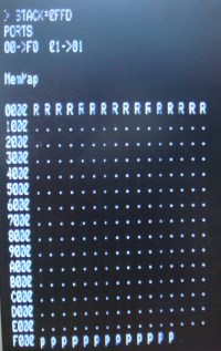
First find the top of RAM, set the stack there and print STACK= xxxxH. 
If there is no valid RAM it will just print STACK= 0000
It will the cycle through all possible input ports from 0FFH down to 0H indicating the value it found (it skips 0FFH values).
It will the print a memory map of all available RAM,ROM or empty space in the 64K adders space.

Here is a typical display:-

Tests Diagnostic Display

The common things that show up here are missing memory or RAM showing up as 'p' for PROM, indicating switch settings are incorrect, more wait states needed for a fast CPU or just plain bad RAM chips.  Unexpected ports can also show here if you did not know about them. Some CPU boards have their own IO ports for various functions.

The code is written to be completely reloadable and will work anywhere is the Z80 adders space. So you can place the EPROM anywhere. This however makes for some real ugly code. I do not use the stack (or any RAM) and has JR 'steps" sprinkled throughout code to get over the 128 byte relative jump distance for the JR opcodes. The RAM therefore does not have to be functional, it will show STACKS=0000 if no RAM is present. 

Unfortunately the 8080 does not have relative JMP codes and so such code would have to be hard wired for a particular location (or possibly use of the stack).  Any decent programmer can easily do something along these lines.  What this program does is give you assurances your video board is working, your input ports (no check for output ports here) are OK and some idea as to how memory space appears to the CPU.

The (ugly) listing of this code can be seen here. The program listing itself can be downloaded here.
 
Use Your Monitor.
When your system crashes your monitor is your best friend.  It allows you to examine memory in detail, set software brakepoints, output test bytes to ports one step at a time and analyze imputs etc etc.  I have continously added, subratcted and generally tweak my monitor over the years. A fairly reason version can be seen on my software page, click here.

Lastly, one of the more difficult hardware problems to solve are those of booting hard or floppy disk systems. This is a whole discussion in itself which I will try to outline at a later date.  Particulary difficult are CPM3 banked systems.   With the introduction of the IDE/Compact Flash S-100 card things should get easier.  Again more on that later.

Other pages describing My S-100 hardware and software.
Please click here to continue...
 

This page was last modified on 01/08/2011